Flight Preparation
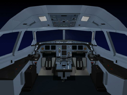
When the A330_200 simulation first starts running, the cockpit is in shut down situation. This allows the aircraft to be prepared for flight just as in the real case. If the users wishes, they may use the Quick Start button to quickly set the aircraft ready for flight.

The cockpit will start up without any lights on, as the no electrical busses will be active.
All displays will be blank, and all light s off. The only exception to this is the Battery Voltage indicator on the electrical panel.

The Battery Voltage indicator is wired directly to the batteries them selves and therefore, if there is any voltage in the batteries, the indicator will register.
Before starting the aircraft, the program must first be set up, as this is a simulation, so the geographical position of the aircraft, and the joystick need to be initialized. Refer to Starting the program for details.
Program Set Up
Select the joystick button
Select the Airport button
After joystick interface and initial position, the cockpit should be checked for its initial state.
Next
Ensure that the program is in the Running State. If not select the “PAUSE” button to ensure the program is operating in the Ruining State.

Initial cockpit set up
|
Item |
|
|
|
Cockpit |
|
|
|
Thrust levers |
|
The thrust levers should be back against the idle stop (joystick thrust lever fully back). |
|
|
| |
|
|
Landing Gear lever |
Down |
|
|
Brake fan button |
As required |
|
|
Nose wheel steering switch |
On position |
|
Lever |
Down, un armed ( spring loaded on the aircraft) | |
|
On |
Assumes blue hyd accum. Pressure is sufficient | |
|
Flaps Up position |
| |
|
|
| |
|
|
IR knobs |
Off |
|
|
Air data buttons |
Off |
|
|
| |
|
|
Engine Fire buttons |
Guarded |
|
|
Squib buttons |
Out |
|
|
APU Fire button |
Guarded |
|
|
APU squib |
Out |
|
|
| |
|
|
Engine pump buttons |
In and guarded |
|
|
Electrical pump On buttons |
Out and guarded |
|
|
Electric pump Control |
In |
|
|
| |
|
|
Engine fuel pumps |
In |
|
|
Center tank pumps |
in |
|
|
Cross feed |
Out |
|
|
Tail Transfer switch |
Mid position (Auto ) it is guarded in the aircraft |
|
|
|
|
|
|
| |
|
|
IDG disconnect buttons |
In and guarded |
|
|
Engine generator buttons |
In (note they will show fault light when electric power is available) |
|
|
Galley button |
Out |
|
|
Commercial button |
Out |
|
|
APU generator button |
Out |
|
|
EXT A |
Out ( may be illuminated as available ) |
|
|
EXT B |
Out ( may be illuminated as available ) |
|
|
Alternate ESS bus |
Out and guarded |
|
|
Bus Tie |
In ( auto) |
|
|
Bat 1 |
Out |
|
|
Bat 2 |
Out |
|
|
Bat APU |
Out |
|
|
| |
|
|
Emergency lights |
Off |
|
|
External lights |
Off |
|
|
APU On/OFF button |
Out ( it is a momentary press spring loaded button ) |
|
|
APU Master button |
Out |
|
|
|
|
|
|
| |
|
|
Pack buttons |
Out |
|
|
Engine bleed buttons |
Out |
|
|
APU bleed button |
Out |
|
|
|
|
|
|
| |
|
|
Turbulence button |
Out |
|
|
PRIM 1 |
In |
|
|
SEC 1 |
In |
|
|
PRIM 2 |
In |
|
|
PRIM 2 |
In |
|
|
SEC 2 |
In |
|
|
| |
|
|
Engine 1 |
Out and guarded |
|
|
Engine 2 |
Out and guarded |
|
|
| |
|
|
As required |
|
|
|
| |
|
|
Engine 1 master switch |
Down position |
|
|
Engine 2 master switch |
Down Position |
|
|
Engine start knob |
Normal |
|
|
| |
|
|
Arm |
Out and guarded |
|
|
On |
Out and guarded |
|
|
|
|
|
|
|
|
|
|
|
|
|
|
|
|
|
|
|
|
Next

Note that on the actual aircraft, if a lever position is not consistent with the displayed position, such as flap lever at 2 and displayed flaps are up, then ground/maintenance crew should be contacted before applying hydraulic pressure to the aircraft systems.


