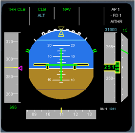
PFD : Speed tape

The speed tape scale
The speed tape scale is from 40 knots to 400 knots. Only a range of 40 knots are shown at any one time. The current airspeed is indicated by the center of the tape which has a yellow line through it. The current Mach number is shown in green at the bottom of the scale, when above 0.4 Mach.
Target Speed
The target speed is a triangle indication on the right side of the speed tape. The speed target is blue if it is the speed target from the FCU selected by the flight crew, or it is magenta if it is the managed speed computed by the FMG.
Speed Trend
The computed speed in 10 seconds time is displayed on the speed tape at all times. This indication is a vertical yellow line with an arrow. The top of the line is the computed aircraft speed in 10 seconds time. The speed trend gives a clear visual indication of the acceleration/deceleration of the aircraft. The trend vector is not displayed when there is little change of aircraft speed.
V Speeds
During the take of phase, the speed tape shows the entered V1, VR and V2 speeds. The V1 speed is shown as figure 1, and the VR speed is shown as small circle. The V2 speed is shown as the target speed . No V speeds are shown, if they have not been entered in the MCDU Performance Take off page, prior to take off.
Limit Speeds
The aircraft limit speeds are shown on the Speed Tape as red and black checkered markings. The limit speeds may be for flap, gear, or VMO or MMO.
Alpha Speeds
The alpha speeds are indicated on the speed tape. They show the minimum selectable speed VLS and the Alpha protection speed. The representation of the alpha speeds varies for the Normal mode and the Alternate and Direct modes for the Flight control system
VFE Next
The next flap lever position speed is shown as an amber equals sign. It appears when the aircraft is below 15,000 ft.
Minimum Flap Retract speed
A Green figure F appears when the flap selector is in position 2 or 3. It indicates the speed at which the flaps may be selected to lever position 1
Minimum Slat Retract speed
A Green figure S appears when the flap selector is moved beyond UP. It indicates the speed at which the flap lever may be selected back to the UP position.


The target speed changes to a split triangle during descent. The upper and lower parts of the triangle indicate the range limits for the target speed. The target speed is adjusted by the FMGS to keep the aircraft on the decent path at idle thrust.

VLS, the lowest selectable speed allowing for an appropriate margin to stall speed

Alpha protect speed. The point where the flight controls will instigate alpha protection mode.
Alpha Max, the highest alpha in pitch normal law.

Next
Previous


