
Copyright D.P. Browne 2011
APU System display
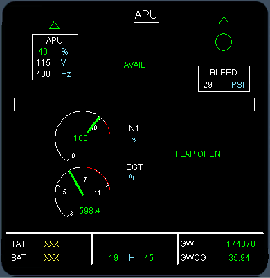
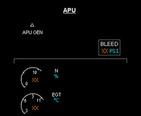
The APU system display shows the APU operating parameters. It may be called up by selecting the APU button on the system display panel on the pedestal.
When there is already AC power available to the aircraft and the APU is started, the APU SD page will automatically appear when the APU is started or if there is any faults associated with the APU, causing an automatic shut down.
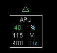
The APU generator display is identical in nature to the other engine generator displays on the electrical AC SD page.
It shows the voltage, load % and frequency of the generated electrical power. When not selected, the APU generator indications are removed.
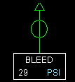
The APU Bleed indications show the Bleed pressure and status of the bleed valve. When not selected the bleed pressure will show zero or amber XX and the bleed valve will display the horizontal bar indicating closed.
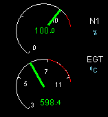
The APU N1 or N (as there is only one shaft) shows the APU engine speed. It is always approximately 100% during use. It may show slightly lower speeds on cold days or higher speeds on hot days, but usually within the range of 97% to 102%
The APU EGT is shown below the N indication. It varies depending upon the load on the APU. If the EGT becomes excessive, it will be displayed first in amber, then in red and then cause an automatic shut down.
When the APU is not running the APU SD page shows amber crosses for the indications.
Next
Previous


