
Copyright D.P. Browne 2011
Electrical System Emergency configuration
There are a number of emergency electrical configurations available during flight, should the engine generators fail to supply their respective AC busses.
Loss of GEN 1
Emergency generator
Static Inverter
Next
Previous
Loss of a single generator in flight causes the ECMU to reconfigure the electrical system to maintain power to AC 1 and AC 2 as well as the AC Essential bus. This is caused by the Bus Tie between the AC 1 and AC 2.
The emergency generator is powered from the green hydraulic system and automatically deploys when needed. There is also an emergency electrical panel from which the emergency generator may be manually deployed.
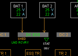
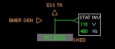
When no AC generator is available to power the aircraft whilst in flight, and the Batteries power the DC essential bus, a static inverter converts the DC voltage supply to 400 Hz AC supply to the AC essential bus.
Flight on batteries only is limited and the batteries will become unusable in about 30 minutes. During this time the flight crew would concentrate their activities on bringing another AC generator on line.
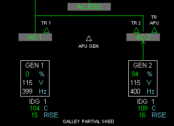
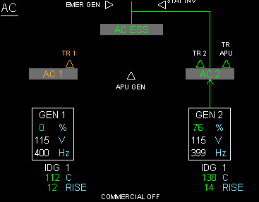
If the bus tie fails the AC2 buss can power the AC ESS bus via the alternate path.
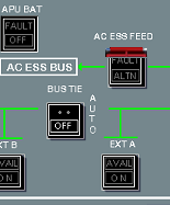
The AC ESS feed alternate path may be deselected on the over head electrical power to isolate any shorting. However this will be advised by special ECAM messages. The Bus Tie button may also be pushed off to isolate the left and right electrical sides.
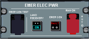
To manually deploy the emergency generator, un-
The emergency generator will supply the AC essential ( and from that ) the DC essential buses. The actual generator is deployed under the right wing. When the flaps are extended, the air flow to the generator windmill is interrupted and the batteries only then power the aircraft until touch down.
The land recovery button, allows the power up of equipment necessary for landing the aircraft. This equipment would have previously been shed to reduce loading on the emergency generator


