Copyright D.P. Browne 2011
Electrical System

AC 1
TR 1
AC 2
DC 1
DC 2
DC BAT Bus
DC ESS Bus
AC ESS Bus
GEN 1
GEN 2
BAT 1
BAT 2
TR 2
TR ESS

AC 1
TR 1
AC 2
DC 1
DC 2
DC BAT Bus
DC ESS Bus
AC ESS Bus
GEN 1
GEN 2
BAT 1
BAT 2
TR 2
TR ESS
APU BAT Bus
APU
BAT
EMR GEN
APU GEN
EXT B
EXTA
TR APU
Static
Inverter
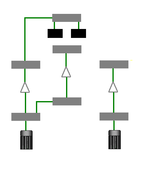
The basic system consists of an integrated drive generator, (IDG)) connected to each engine.
Each IDG supplies AC electrical power to its respective AC bus, AC bus 1 and AC bus 2
A Transformer Rectifier (TR) converts the 400 Hz AC supply to a DC voltage to power the DC buses, DC 1 and DC 2
An Essential AC and DC bus are normally supplied by the AC 1 bus. The AC buses, have a variety of means to supply them but are normally supplied by AC bus 1
The Batteries (1 and 2 ) are normally kept charged from the DC 1 bus. In the event of no AC power generation available, the batteries can supply the aircraft with essential power via the DC essential bus and the Static inverter for about 30 minutes
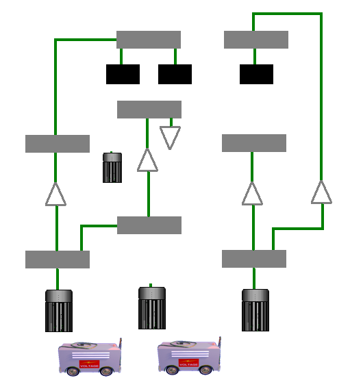
In addition to the basic system there is an APU generator, and the ability of two external supplies to the aircraft. These supply the AC 1 and AC 2 busses. The APU may be used on the ground or in the air.
A TRU APU supply DC current to the AP battery. The APU may be used to start the APU if no external power is available.
An emergency generator, driven from the green hydraulic system is available to supply AC power to the AC essential bus
In the event of no AC power generation in flight, a static converter can generate AC power to the AC essential bus from the DC essential bus. The batteries would be connected to the DC essential bus in this case.
Basic System
Complete System
The electrical system is multi configurable in the event of loss of electrical power in parts of the system. Load shedding is automatic and the configuration is controlled by 2 Electrical Contactor Management Units ( ECMU 1/2) .
The flight crew interface with the EMCU 1/2 and the electrical system via the overhead electrical panel.

Next


