

Setting up the Simulation Computers
The various simulation components may be run on separate computers. The Main PC runs
the A330-
Each simulation component communicates via a windows shared memory data block. The structure of this data block must be the same on every computer used in the simulation.
The Shared Memory identification is shown in the title bar of each VS Simulation component. The number is typically a 3 digit value such as 3.6.7 or 4.8.1 It must be the same for each simulation component. If it is not, please down load the latest versions of the software.
A program called the VS Simulator Transceiver is run on each of the computers used in the simulation, to copy in/out the appropriate parts of the windows shared memory data block. The VS Simulator Transceiver works by reading its corresponding ini file to determine what data it will send/receive and to which computer.
Determining the IP address
Pre amble :
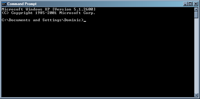
On the each of the computers used in the simulation run the CMD prompt program.
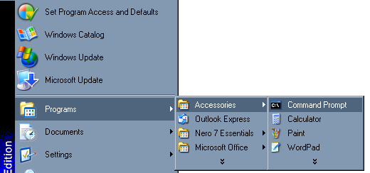
This will bring up a DOS looking like edit box.
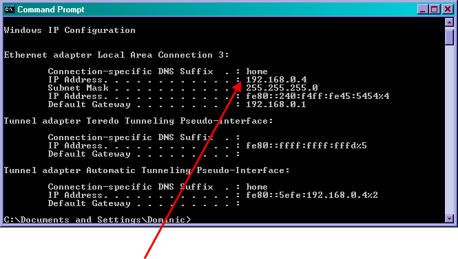
Type “ipconfig”
The IP address of the computer is shown. (192.168.0.4 in this example)
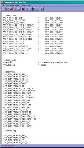
Edit the VS Simulator Transceiver Ini file in each computer to enter the required information. The file is located in the directory “C:\Program Files\VitalSimulation\AddOns “ and is called “Transceiver .Ini”
The file may be edited using Word or Notepad.
The file has 4 sections.
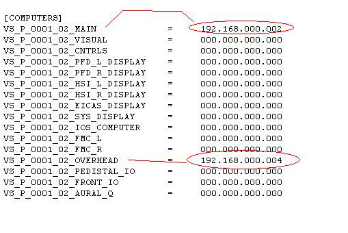
The fist contains the IP addresses of al the computers that are used in the simulation. This list must be the same on every Transceiver .Ini file.
If some computers do not exits simply put 000.000.000.000 next to them to remove them from the simulation.
The next part is for a log file. This is rarely used. Setting the log file to TRUE would produce a log of the data communication. It should only be used for trouble shooting
The next part [Transmits] lists the data blocks that are to be transmitted from this computer.
The last part [Receives] lists the data blocks that are to be received by this computer.
For each computers ini file, set its IP address .
The A330-
In this example, there are 2 computers being used in the simulation, the Main and the overhead.
The main computer has the IP address of 192.168.0.2 and the computer running the overhead simulation has an IP address of 192.168.0.4
Note that for later versions of windows, the IP address can not have leading zeros on the last element.
So its 192.168.000.16 not 192.168.000.016
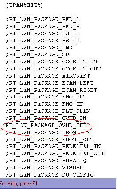
For each computers ini file, set its Data Transmission block(s) I
In this example it is the computer running the overhead panel simulation. It will transmit the OVHD_OUT data block.
Correspondingly the Main PC will receive the OVHD_IN data block and so its Ini file will have that data block uncommented (;) and the OVHD_OUT block commented out (;)
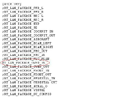
For each computers ini file, set its Data Receives block(s)
In this example it is the computer running the overhead panel simulation. It will receive the OVHD_IN data block.
Correspondingly the Main PC will receive the OVHD_OUT data block and so its Ini file will have that data block uncommented (;) and the OVHD_IN block commented out (;)
Please be aware that the VS Transceiver sends UDP data packets to the IP Address
that you set up at a rate of 20 -
The simulation aircraft type is set to A330 or A320 in the ini file.